|
|
 |
Special projects
Re-erecting the Obelisk in Caesarea
Yoram Sa‘ad
|
In the second century CE a large facility for chariot races (hippodrome in Greek, circus in Latin) was constructed in the eastern part of Roman Caesarea. This facility replaced ‘Herod’s Circus’, which was built in the western part of the city. A fallen obelisk and three conical columns made of red granite (Aswan granite) were discovered in the center of the arena in the eastern hippodrome. The obelisk was found broken, in three pieces . Due to the importance and uniqueness of the obelisk it was decided to re-erect the monument in its original location. [1]
|
|
Re-erecting the obelisk in the Eastern Hippodrome of Caesarea [2]
The Caesarea obelisk is the only one of its kind known to exist within the boundaries of the State of Israel, and thus re-erecting it was an unprecedented project. In light of this the Israel Antiquities Authority (IAA) convened a conservation committee, which was intended to serve as a professional-public advisory body for the purpose of discussing the subject in principal. Approximately fifty professionals participated in the committee, among them historians, archaeologists, architects, engineers and conservators. The committee was presented with different planning options and preliminary architectural-engineering aspects that required implementation. In addition, the committee addressed issues concerning professional ethics.
A vast majority of the conservation committee approved the recommendation to re-erect the obelisk in its original location, as proposed by the IAA. The management of the IAA appointed what was then the Caesarea Conservation Project team, headed by the conservator Y. Sa‘ad and engineer L. Sukhanov, to implement the plan.
|
The Obelisk: Data and the Monument’s State of Preservation
|
 |
|
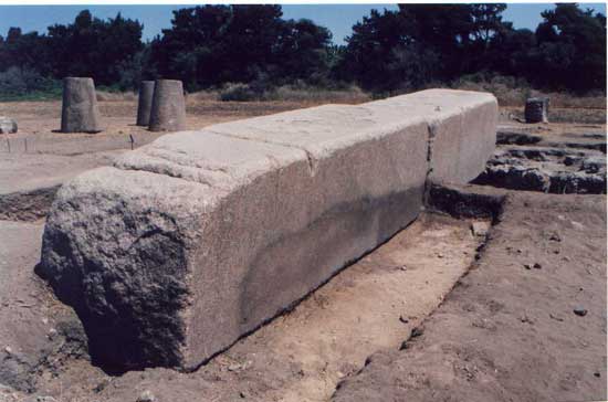
The obelisk after the trial excavation conducted by the Israel Antiquities Authority.
|
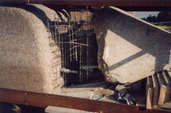
The project of re-erecting the obelisk began with a trial archaeological excavation that was directed by Y. Porath in the vicinity of the fallen monument (Porat 2003: 34-35; Porath et al. forthcoming); this was in fact a resumption of the excavations that were previously conducted there by the Joint Expedition to Caesarea Maritima (Humphrey 1986: 477-491). The results of the trial excavation revealed that the obelisk had originally been placed on a foundation that was situated approximately in the center of the arena, on top of the partition wall (spina) that was built along the longitudinal axis of the arena. The foundation was constructed of rubble and lime-based mortar (debesh) and was made thicker in the section that bore the obelisk. A large piece of granite measuring 1.20 x 2.20 x 2.20 meters was discovered in the hippodrome’s arena, north of the fallen obelisk. After having compared it with other parallels from the classical world, Dr. Yoseph Porath and Dr. Peter Gendelman concluded that the obelisk was positioned on a large box-shaped pedestal and they suggested that the piece of granite was such a pedestal; however, there is no definite, proven connection of this. The obelisk fell or was toppled from the pedestal onto the floor of the arena north of the spina. It is believed that because of its great weight the obelisk remained in the spot where it originally fell. Saw marks were discerned on the obelisk’s eastern face, which was the top side of the monument in its fallen state.
|
 |
|
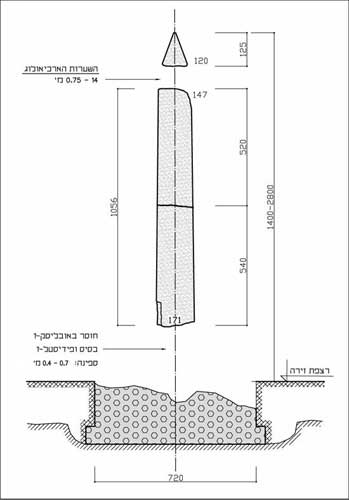
The parts of the obelisk that survived. Courtesy of L. Sukhanov (engineer).
|
The trunk of the obelisk has a square cross-section and it tapers about 2.3 centimeters per meter of height toward the top. The obelisk’s capstone, called the pyramidion, is shaped like a square pyramid with sides that are at an angle of almost 60º.
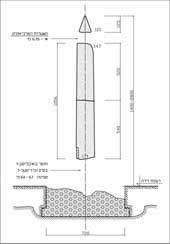
The obelisk broke into three pieces when it fell: two sections of the trunk that remained in situ and an upper part of the trunk together with the pyramidion. The two sections of the trunk were found in the area (total length 10.56 m, bottom cross-section 1.71 m, top cross-section 1.47 m) with a matching fracture between them, and separate from them was a part of the pyramidion (height 1.49 m, bottom cross-section 1.20 m; see Humphrey 1986: 486, Fig. 240). The bottom and top of the obelisk’s trunk were found broken. The extent of the missing parts is unknown; however, it was estimated that it was not less than one meter in each section. The vertex of the pyramidion is truncated and its bottom was broken above the point where it was connected to the obelisk’s trunk.
Based on a calculation of the angles of the pyramidion’s faces, the length of the missing part between it and the trunk was not less than 0.5 m. The total length obtained for the obelisk, together with the completion of the missing parts, was at least 12.50 m and a maximum of c. 25.00 m. According to the scale of the crane that was used to hoist the pieces of the monument the bottom part of the trunk weighs c. 45 tons while the upper part is c. 36 tons. With the additional weight of the pyramidion and that of the missing parts the total weight of the obelisk was approximately 100 tons.
Slight depressions and protuberances were noted along the sides of the obelisk’s trunk. The surfaces of the sides are not planar but slightly curved. The lines of the corners running the length of the obelisk’s body were wavy as a result of the distension and distortions in the granite. A slight geometric deviation (deformation) was detected in the longitudinal axis of the obelisk’s trunk. Sawing and quarrying marks were noted on the upper side of the obelisk when it was lying in its fallen position, as well as along the edges of the pyramidion.
|
The Architectural Planning
|
|
The initial architectural planning proposed the following principles regarding the appearance of the obelisk and its immediate surroundings:
· The foundation will be reconstructed and a base will be built above it.
· A pedestal will be constructed above the base that will be similar in size to the granite base that was found at the site.
· The sections of stone that are missing from the bottom of the obelisk’s trunk will be completed with minimal restoration so as to make the sides of the trunk straight.
· The two broken parts of the trunk will be connected together.
· The stone that is missing between the obelisk’s trunk and the pyramidion will completed to the minimum extent required in order to connect the profile lines of the trunk with those of the pyramidion.
· The pedestal and the completion of the missing parts of the obelisk will be covered with a material that closely resembles the appearance of granite, but in a manner that will make it possible to differentiate between them.
|
The Engineering Planning
|
|
Strict adherence to the principles of conservation, the need to ensure the stability of the obelisk after re-erecting it, devising technical solutions for the necessary completion of missing stones and solutions for raising and anchoring the broken parts – all of these led to a reoccurring need to seek out creative solutions for the execution of the project.
In the first stage we examined preferred methods for assembly; each method dictated a different implementation procedure. It became apparent that there were two possible options for assembling the parts of the obelisk:
1. Assembling it on the ground with the obelisk in a horizontal position and erecting it in one piece.
2. Assembling it in stages – placing the bottom part in position first followed by the upper part.
Doubts concerning our ability to ensure matching and accuracy in assembling the parts in a horizontal and stationary position due to the asymmetry of the obelisk’s trunk and the weight of the parts etc, resulted in our selecting the second option which afforded us control in most of the implementation phases including the possibility to make modifications and corrections during the erecting process.
The detailed engineering planning included specific construction planning, and load and stability calculations for earthquakes, wind, vertical load etc. The planning included developing complicated methods of measuring and determining the suitability of materials (for example: adhesives, metals, concrete, injected materials, etc).
The assembly process included numerous variables, some of which were known in advance and some which only became apparent as the process progressed. Other difficulties were discovered when it became clear that no Israeli standard exists for calculating stone substances, and because of the irregular shape of the monument (the obelisk). It was for these reasons that calculation methods needed to be developed during the implementation process.
|
 |
|
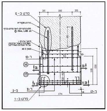
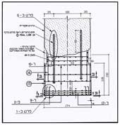
Reinforcement specifications of the lower completion casting. Courtesy of L. Sukhanov (engineer).
|
Surveying, Marking and Drilling
The engineering planning called for completing the stone which was missing from the obelisk’s body with cast concrete. In tests that were conducted to ascertain the adhesion properties of concrete to granite, it became clear that the concrete bond was weak due to the crystalline structure of the granite. It was decided that titanium rods, which are impervious to rust, would be installed between the two broken pieces of the monument and in the connections between the concrete completion castings and the granite. It was also determined after consulting with experts in the field that the concrete castings should contain an additive of special nylon fibers the purpose of which was to prevent the concrete castings from cracking and shrinking.
The drillings in the obelisk’s trunk and the pyramidion that were intended to connect the completion castings by means of the titanium rods did not call for a great deal of accuracy. On the other hand the drilling in both sides of the break in the main obelisk required maximum precision. The difficulty we encountered was in transferring the drilling data (location, angle and axis) from one side of the fracture to the other side. It was for this reason that a drilling fixture was constructed that was especially suited for this task. The depth of the drilling that was done is as follows: c. 0.80 m at the bottom of the shaft, c. 0.30 m at the upper end, c. 0.15 m at the bottom of the pyramidion.
When the drilling was being executed it became apparent that penetrating the outer layer of granite to a depth of c. 0.10 m was relatively easy; however, the deeper the drilling went the more difficult and slower it became. This phenomenon repeated itself for each of the drillings. A possible reason for this is that the outer layer of stone was weakened as a result of the weathering processes the monument had undergone over the course of time.
In order to select the most suitable adhesive the technical specifications of a number of leading companies in the field were checked. The main criterion we were concerned with was the adhesive’s long-term durability factor; its strength was a secondary criterion. This was because most kinds of epoxy glues have a higher adhesion strength than the shearing strength of granite; however, they have a tendency to “age” quickly. Since we were unable to find any data standards for the proper adhesion strength for either titanium or granite (different fields), we were obligated to carry out a series of experiments with scaled-down models in testing laboratories. Upon completion of the tests the adhesive, Scotch Weld 1838 b/a, was selected, which is manufactured in the United States and is used in the aeronautical and space industries. This adhesive is highly resistant to the environment because it uses a polyamide accelerator. Data exists regarding the adhesion strength between titanium and titanium.
|
|
Pouring the Foundation and Pedestal
The original foundation of the obelisk was built of fieldstones and lime-based mortar and was found to be unstable and some of it was missing. For the purpose of building a new foundation a pit that measured approximately 2.0 x 4.0 m was excavated in the center of the original foundation. The sides of the pit were lined with lime-based mortar so as to isolate it from the concrete. The concrete casting contained 35 cubic meters of B200 concrete. After the concrete hardened the pedestal, measuring 1.50 x 4.00 x 4.00 m, was poured on top of it; this casting contained 27 cubic meters of B400 concrete. Stainless steel rods were utilized to reinforce both of the castings and an additive of nylon fibers was used to prevent them from shrinking and cracking. A concrete vibrator was used in order to ensure that the concrete components were evenly distributed throughout the volume of the castings.
|
|
The Bottom Part: Casting the Completion
In order to ensure the stability of the obelisk it was decided to execute the completion casting that was planned for the bottom of the obelisk’s body such that it would also comprise the base. We planned on pouring an encasement casting for the aforementioned completion after the bottom part of the obelisk was positioned on the pedestal. The casting would be anchored to the pedestal thereby creating a kind of cup inside of which the obelisk would stand. In this fashion we could achieve a simulation whereby the obelisk is seen to be standing on a base.
A solution was devised to ensure the vertical plumbness of the bottom part while it was being set in position. This involved affixing rustproof stainless steel plates to the corners of the bottom part of the obelisk’s completion casting. While erecting the bottom part of the obelisk these plates were meant to rest up against parallel plates in the pedestal, thus it would be possible to insert additional shims of any required thickness between the anchored plates in order to attain verticality.
|
 |
|
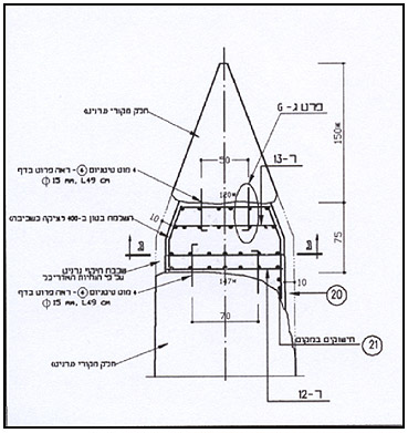
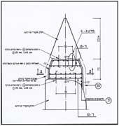
Reinforcement specifications of the upper completion casting. Courtesy of L. Sukhanov (engineer).
|
The Upper Part: The Completion Casting
A preliminary question we had to address was how to establish the original location of the sides of the pyramidion relative to those of the obelisk’s body. The solution was found when we noticed a saw mark along the edge of one of the sides of the pyramidion. We assumed that this cutting was probably used to detach the pyramidion from the trunk after the obelisk fell and therefore it indicates the upper side of the fallen monument. The pyramidion and the upper part of the obelisk were joined by means of a completion casting when the pieces were in a horizontal position. The pyramidion was placed approximately 0.70 m from the upper end of the obelisk’s trunk after examining the planar projections of the sides. A mold was built in accordance with the calculated angles in the gap between the two stone masses and the completion casting was executed using B400 concrete. Stainless steel rods were used for reinforcement in each of the completion castings. The castings receded several centimeters from the actual perimeter lines in order to leave room for the covering element. To prevent oxidation from occurring at the contact points between the different type metals in the castings (titanium and stainless steel) the metals were wrapped with two layers of nylon insulation .
This stage required making decisions the results of which we would only see after having finished erecting the obelisk and removing the scaffolding and other constructions.
|
|
Supporting Fixtures
The unfavorable data regarding the adhesion of concrete to granite was cause for concern. We believed that the effort that would be exerted when lifting the obelisk’s parts would cause the completion castings to separate where they were connected to the granite. In order to prevent such a situation a number of steps were taken.
The parts of the obelisk were “encased” in support fixtures that were assembled from steel right-angle members that were positioned in the corners of the parts and were connected with welded metal strips.
In order to prevent the parts from shifting inside the fixtures the latter were anchored to the concrete in the completion castings. To improve the fixtures’ grip on the body of the obelisk “cement grout” was injected between the right-angle members and the completion castings. Wooden wedges were inserted between the right-angle members and the granite.
In addition a support was built utilizing concrete and stones as a fulcrum beneath the center of gravity of the concrete completion. Piles of beach sand were placed at the bottom end of the parts to reduce friction and the possibility of crushing which were anticipated during the transition phase when moving the object from a horizontal position to a vertical position.
|
 |
|
The connection of the pyramidion to the upper part of the trunk.
|
Positioning the Bottom Part and the Encasement Casting (Base)
In order to lift the parts of the obelisk a special steel frame was built which was adapted to bear the weight and size of the obelisk’s body. The frame was affixed to the parts of the obelisk while they were still in a horizontal position.
Prior to December 5, 2000, the day which was designated for erecting the bottom part of the obelisk’s body, a carrying frame was assembled around it and iron chains were connected from one side of the body to the other, by way of underneath it. The chains were tightened and the links were counted to ensure the body would be plumb after lifting it. The cables of a crane with a 450 ton lift capacity were connected to the carrying frame .
|
 |
|
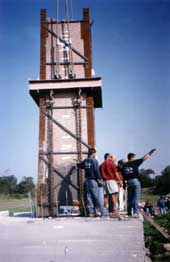
The lower part of the obelisk positioned in place.
|
The lifting operation was accompanied by considerable apprehension because of possible errors but in the end the procedure went smoothly. The bottom part of the obelisk was placed on the support surfaces (the stainless steel plates) that were on the pedestal. In order to measure the verticality of the body the center axes, which were marked on the sides of the obelisk, were used with the aid of two theodolites that were positioned east and north of the pedestal. The calibration of the instruments was done on the axes that were transferred beforehand to the pedestal. Based on the measurement, adjustments were made by inserting stainless steel shims between the support surfaces .
The last measurement showed that the north south axis was precisely calibrated while along the east west axis there remained a minute deviation of the upper part to the east (c. 12 mm). After having consulted with the crane operators and experts in bridge construction who were present at the site and in light of the asymmetry of the obelisk’s body, we decided not to attempt to make any further corrections.
Preparations for Erecting the Upper Part
This was the most difficult stage of the assembly process. Different ideas were evaluated and rejected due to reasons such as budgetary constraints, the conservation damage to the obelisk’s trunk and other reasons. The preferred solution from our standpoint was cinching it around the sides which would not necessitate further damage to the original body. In calculating this option it became clear that in order to lift a body that weighs 50 tons it is necessary to create lateral pressure of 100 tons (a 0.5 drag coefficient). All of the details of the cinch were planned including the friction materials; however, the weakness of the outer layer of the granite body became evident at this point and we became concerned that when the obelisk was lifted the outer layer of stone would be squashed and the body of the monument would slip out of the cinch.
We considered a solution that included: grasping the upper part of the body with lifting straps connected to the carrying frame in a manner similar to grasping the bottom part, placing it on the supporting points that would be located along the plane of the fracture and filling the fracture’s void with adhesive material. To determine the location of the supporting points we needed precise matching measurements of the surfaces of the fracture on both sides of the break. An error of one centimeter in the height of the supporting points was likely to cause a deviation of about 8 cm at the upper point of the obelisk’s vertical axis.
|
 |
|
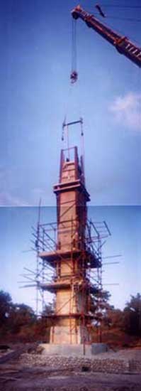
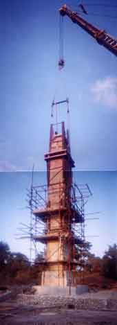
Hoisting the upper part.
|
Another basic problem which we had to solve at this point was how to ensure the horizontal and vertical plumbness of the upper part of the obelisk. We examined the idea of supporting the obelisk on a central fulcrum so as to circumvent the difficulty of precisely measuring the two parts of the fracture, which also provided a solution for the problem of verticality. The fulcrum that was considered is made of reinforced rubber called Elastomer. It is 25 cm in diameter, has with a vertical load bearing capacity of approximately 60 tons and is used in bridge construction. Its location in the center of the fracture plane – on the axis of the center of gravity – makes it possible to adjust the vertical plumbness by means of exerting a small horizontal force. This solution did not require matching the parts on the fracture’s surfaces.
After repeated tests the idea of using a central fulcrum was rejected because we feared that the flexibility in the steel beams of the horizontal leveling frame and the flexibility of the crane’s suspending system would not allow us to keep the upper part of the obelisk motionless for the period of time it would take for the concrete to harden.
We returned to the option of the supporting points. In order to calculate the necessary height for the supporting points we needed to examine the fit of the two parts of the fracture. The square cross-section of the obelisk in the region of the fracture measures c. 1.60 x 1.60 m. The slope of the fracture is c. 0.40 m from the highest point to the lowest point. The surface of the fracture is crystalline. The height of the supporting points depended on how much of the match was missing and the angle of the surfaces of the fracture.
The supporting points were fixed in parallel locations along the surfaces of both parts of the fracture. The points consisted of stainless steel plates that measure 2 x 12 x 12 cm. A layer of epoxy grout was poured below the plates in order to prevent localized concentrations of exerted pressure. We estimated that when we erected the upper part in its place it would stabilize on three points which define a plane; therefore two supporting points were located along the axis of the center of gravity and the other two could be shifted so that the axis of gravity would extend the distance between the points .
|
 |
|
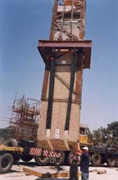
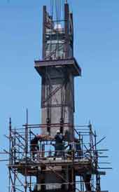
Positioning the upper part still connected to the crane.
|
Erecting the Upper Part
After having devised a solution for the supporting points we had a reasonable assembly procedure from a planning perspective. The following details had been determined: grasping the upper part, the support, horizontal and vertical plumbness, the initial stabilization, releasing the suspension from the crane and injecting the adhesive into the void of the fracture.
All that remained was the question of how to ensure that the lifting straps did not become caught in the void of the fracture that was between the two parts of the obelisk. The shape of the fracture required a larger gap between the parts; however, in light of the shape of the obelisk’s trunk such a gap would cause the formation of a step in the planes of the sides. In addition to this, a large gap reduces the constructive stability of the obelisk and impairs the quality of the adhesion between the parts. In order to overcome this problem we were compelled to saw channels in the bottom of the upper part of the obelisk where the lifting straps were located.
In order to obtain quality adhesion of the rods inside the drillings it was decided that the diameter of the titanium rods was to be 45 mm and that of the drillings 50 mm. This meant that millimeter precision was required in inserting the rods in the drillings when erecting the upper part. The manual measurement of the match of the fracture’s surfaces was reasonable considering the conditions under which it was conducted, but its accuracy was not certain. We had to be prepared for a situation in which the rods could not be inserted into the drillings. In addition to this there was the concern that in light of the minute tolerance between the rod and the side of the drilling (2.5 mm on either side) we would not be able to make any adjustments that might be required to the verticality of the obelisk’s trunk. We therefore decided to widen the diameter of the drillings at the end of the bottom part of the obelisk. This decision necessitated achieving a maximum quality of adhesion between the two parts of the fracture as a constructive requirement .
|
 |
|
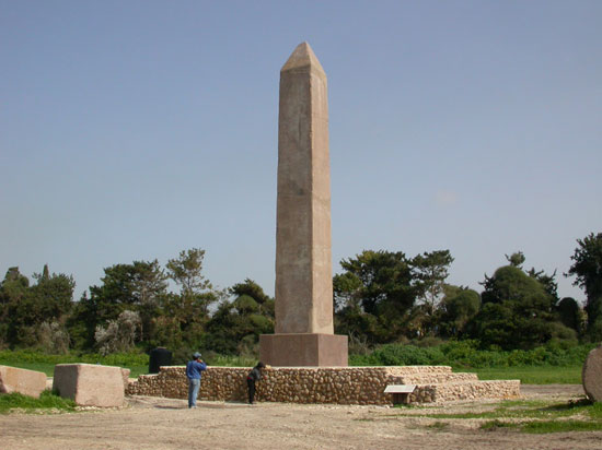
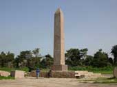
The obelisk after being re-erected.
|
We anticipated the possibility that the upper part would not be straight after raising it initially. We estimated that by tilting it 5-6 cm to either side we could lower the upper part of the obelisk into the steel guide frame that was fabricated for this purpose. In order to achieve the necessary verticality in a situation where there is considerable deviation, a fixture was built to tighten the lifting cables. This fixture was connected to the crane’s suspending system and steel weights were prepared that were meant to be suspended from the sides of the obelisk. The causes for concern due to errors when erecting the lower part of the obelisk were also valid when raising the upper part; however, in the latter instance there were additional factors to be considered. A slight wind would make erecting the obelisk impossible. If the upper part was to swing in the air the rods that protrude from its bottom were likely to break as a result of striking the lower part of the obelisk. In addition, the question arose regarding the safety of any personnel standing on the scaffolding during the erecting. It was decided that in case of wind the erecting would be postponed and at the time when the upper part was being hoisted into place no one would be allowed on the scaffold.
The upper part was erected on June 18, 2001. After raising it into position the longitudinal axes were measured to determine the plumbness of the obelisk trunk. When it became clear that there was an inclination of c. 12 cm several attempts were made to remedy this condition that included utilizing weights, tightening the lifting cables and adding/removing connecting rings in the crane’s suspending system. In order to make the adjustment the upper part of the obelisk was laid on the ground a number of times; however, the inclination did not improve significantly.
At this point we decided to hoist the trunk to the designated position and try to stand it in place. The trunk was lowered into the guiding frame and using wooden wedges that were inserted between it and the frame the outer planes of the sides of the two parts of the obelisk were aligned. As expected, the trunk stabilized itself on the three supporting points (the western, northern and southern ones) while at the same time the titanium rods were inserted into the holes of the drillings .
Upon releasing approximately 35% of the load from the crane, as was determined beforehand, the lowering of the upper part was halted in order to measure verticality using the two theodolites which were placed in an identical location when the lower part of the obelisk was being erected. The measurement showed that the axis of the trunk was inclined about 40 mm to the north. No inclination was measured in an east west direction. There was a space of 5 mm at the eastern supporting point. Calculations were made for the required adjustment after which we added a 9.5 mm stainless steel shim to the northern supporting point, a 10 mm shim to the eastern supporting point and a 5 mm shim to the western supporting point. The final measurement showed that the obelisk’s longitudinal axis was perfectly plumb.
|
Coverings for the Castings and the Completion of the Project
|
 |
|
|
The last stage of the re-erecting procedure involved covering the stone completion castings on the body of the obelisk. The base was supposed to be covered only after the scaffolding was removed.
After examining the matter we had two options:
1. Utilizing a covering made of prepared sheets/plates (granite, imitation granite).
2. Covering the castings using an application technique similar to that of plaster and applying an outer coating.
Option No. 1 was rejected when it became apparent to us that the availability and the cost of industrial imitation granite sheets were prohibitive. There was also the concern that the sheets would be sensitive to the climate and could be vandalized in the existing conditions of the open field. We decided to try and produce a mixture of materials that would be suitable for the application of Option No. 2. A number of samples were executed in order to check the composition, adhesive materials and the external appearance.
The mixture that was selected included crushed granite – aggregates up to 4 millimeter in size; crushed limestone – aggregates up to the same size; and acrylic (33) diluted in water. The mixture that was achieved has a general appearance similar to that of the obelisk’s granite; nevertheless, one can still discern the difference between them. The application of the covering was done by receding several millimeters compared to the original surface.
In order to protect the monument from sand storms, the formation of salts and other environmental/climatic weathering factors the surfaces were treated with Rhodia H224, which repels water but is porous enough to allow vapor to escape.
At the end of the treatment the scaffolding that enveloped the monument was dismantled and the obelisk was entirely exposed for the first time, without any disturbances to its facades. At this point the project was halted. Its continuation beyond the planned schedule was caused because of unforeseen problems throughout the entire period of execution and this exhausted the budget. The finished covering to the base of the obelisk and the completion of the reconstruction of the partition (spina) were postponed until the beginning of 2004. With the execution of these final measures (in January-February 2004) the project of re-erecting the obelisk came to an end .
-------------------------------------------------------------
[1] Re-erecting the obelisk was made possible through a generous contribution donated by the Stoll and Feldman families, and with assistance from Kibbutz Sedot-Yam. The project was funded by the Stoll and Feldman families, Caesarea Development Company, Government Tourism Company and the Israel Antiquities Authority.
[2] This article is based on the implementation report which is on file in the archives of the Israel Antiquities Authority. The project of re-erecting the obelisk was conducted between May 2000 and August 2001. The project was executed by the following individuals under the guidance of J. Scheffer (engineer); Y. Sa‘ad –project director; L. Sukhanov (engineer) – engineering planning and implementation guidance; I. Keidar (architect) and S. Puni (architect) – architectural planning; V. Assman, A. Hajian and A. Levitt – surveyors assisted by A. Yamim and F. Mark; also participating in the implementation – Y. Marom, S. Akiva, S. Sabadini, V. Backman, A. Janach, H. Abramov, L. Hanukaiev, R. Abu-Diab, J. Neguer, Y. Kotler, H. Yezaiev, T. Woodi, E. Mabreto, A. Gelber, A. Kuperstein, D. Sibony, L. Matatov and M. Goash; M. Deutscher and Z. Ginat – administrators.
|
|
References
J. H. Humphrey 1986. Roman Circuses, Arenas for Chariot Racing. Berkeley and Los Angeles.
Y. Porath, 2003. Installations for Exhibition, Racing and Athletics at Caesarea. Qadmoniyot 125:25-42. (Hebrew).
Y. Porath, P. Gendelman, R. Gersht and G. Bijovsky, forthcoming: The Excavations of the Israel Antiquities Authority in the Eastern Hippodrome, Caesarea, ‘Atiqot.
|
|
|
|
|